DJI Phantom 4 RTK
Recommended Field Workflow for RTK Processing
This guide explains how to use the Phantom 4 RTK and DRTK2 Moblie Base Station in parallel to collect RTK data. The P4RTK mission planning setup on the controller is exactly the same, and can be found at https://www.aerotas.com/creating-flight-paths-phantom-4-rtk. Our testing has shown that utilizing the D-RTK2 produces more reliable results than the PPK workflow. This guide will begin as if you are ready to set up your equipment in the field, and fly.
Required Equipment
Phantom 4 RTK
DRTK2 Moblie Station
P4 Intelligent Flight Batteries (charged) (enough for the flight plus a few extra for redundancy)
At least 2X WB37 Batteries (charged) (one for controller one for base station recommend more for redundancy)
Crystal Sky controller
SD Cards
Phantom 4 RTK Surveying Checklist
Field Collection procedures
In the field a Minimum of 3 GCPs clearly and precisely visually represented are required for this type of flight.
DRTK2 Base Station, Controller, and Aircraft
The first step is going to be to setup the DJI base station. You will want to set it up in an area free from obstruction, with ample direct access to the sky and with minimal interference (away from buildings, trees, cars, power lines, etc.). It is not necessary to setup the base station over a known point.
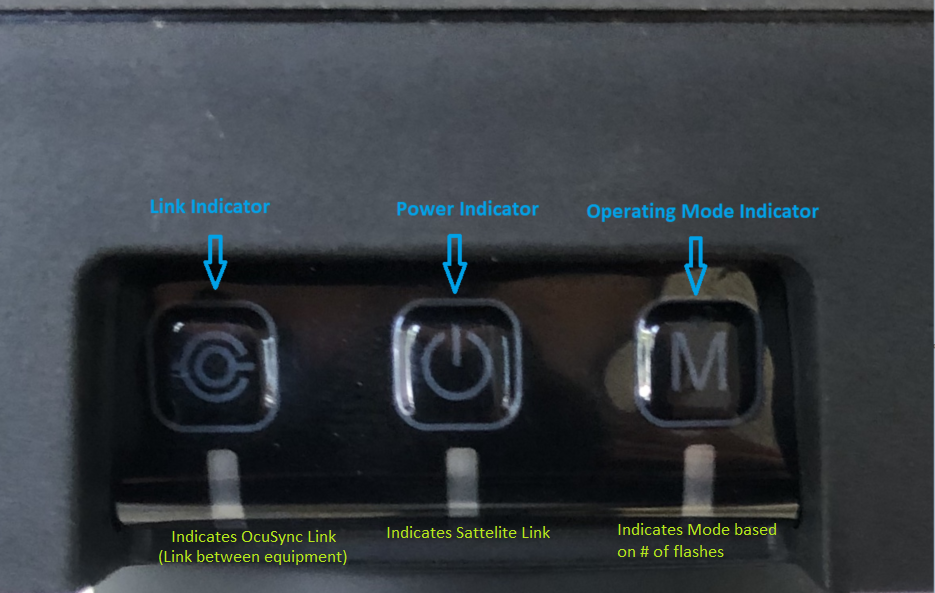
The DJI base station has 3 buttons/indicator lights, pictured below.
D-RTK2 buttons and indicator functions.
After you have found a suitable location; using the middle button, power on the DJI base station using the same methodology as all DJI products (tap tap and hold until the unit powers on). You will hear the internal fan start whirring when the device is on, let the system initialize.
Once initialized you should see 3 lights. The “link indicator” should be red, and the “power indicator” should be green (it may blink red at first which indicates low satellite signal, that is ok, it should find enough during the rest of the setup and eventually turn green). The “operating mode indicator” should be on Mode 1, represented by a slow, single flash. If it is already, no further action is required, however if it is flashing 2x rapidly, or 3x rapidly, or not at all, you will need to press and hold the mode button until the mode has changed.
**Important**- Do NOT move or turn off the base station for the remainder of setup and flight. The base station should be the first piece of equipment setup and turned on, and the last piece of equipment turned off and moved. ***
Next, power on your controller. The controller will need to be linked to the Mobile station.
Tap “fly” on the controller main screen, and go to the general settings menu in the upper right hand corner of the screen and open the “RTK” menu. Make sure RTK is turned on. For RTK service type, select “D-RTK2 Mobile Station”. The unit should link up automatically.
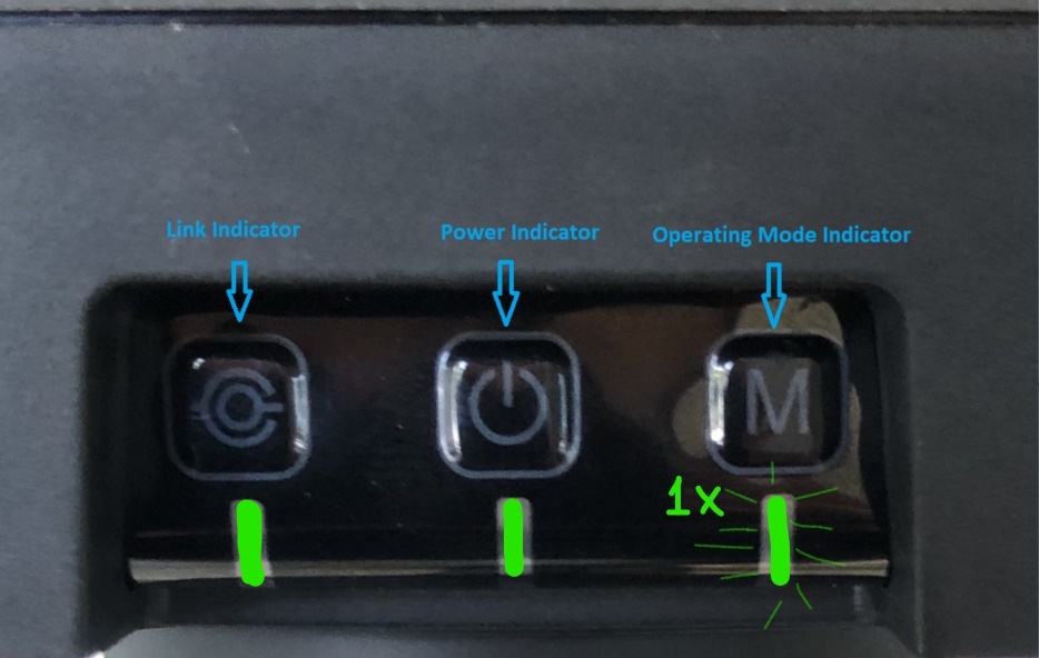
If the unit does not link automatically, click the “linking” button at the bottom, and press the link button on the mobile station, it should start to blink red and green rapidly to indicate linking. Once linking is successful, the remote controller indicator and the Link indicator should be solid green. If the indicator is flashing green, this means it is connected, but has a less than optimal OcuSync signal.
When operating as intended, after initialization and controller link, status lights should look like this.
Now turn on the aircraft.
If the aircraft does not link automatically, you will have to manually force the link.
To re-link the remote with the aircraft, select “link to aircraft” on the pop up, or tap the “?” next to the prompt that states “aircraft has been disconnected”.
If neither of these options work, try linking the aircraft through the RC menu page (denoted by the controller icon), this will disconnect the D-RTK 2 mobile station. After aircraft link, go back to the RTK page and select the “D-RTK 2 mobile station” for service again, and it should link back up without de-linking the aircraft.
After the aircraft is linked, it may throw errors and claim that it cannot take off. Let the system sort itself out for a minute or two, do not turn off the aircraft or base station during this time. Wait for the status bar to turn green and for the RTK status on the HUD to display “RTK FIX” on the top status bar.
Double check the status on the controller and the status lights on the base to ensure connections one last time before mission commencement.
Fly the mission
Now that the system is set up, all indicators are green, and you have selected your desired mission, you can begin the mission.
Throughout the flight the status bar should stay green, and the RTK signal lock should be strong and also stay green as pictured below.
If for some reason you get an RTK signal error, you can pause the mission, and wait for the system to re establish an “RTK FIX”. If you continue the mission without an “RTK FIX” the photos being taken will not contain the RTK data, and will have to be processed PPK. If pausing doesn’t seem to work, try bringing the drone back via the “return to home” button and reset the drone and resuming the mission from the abandonment point.
RTK Fix status should remain on and connected throughout flight.
battery swapping
If you are using the P4RTK you are likely flying multiple battery missions. If you have to return the drone to home using the “return to home” function, an abandonment point will be recorded.
When the drone returns, only power down the drone, leaving the controller on, and swap the battery. Your mission plan with abandonment point should remain on the screen the entire time.
After the drone has powered back up, it will likely throw error codes much like it did initially, before showing a green status and “RTK FIX”. Give the system a minute to work through all of this.
To resume the mission, tap the document icon on the left side of the screen while in the mission HUD, and select the mission you are currently flying. If the document icon is not showing up, try tapping the screen or pulling left to right with your finger on the screen.
The screen should now give you the option to “invoke” the mission again, and should resume from the abandonment point.
Continue to monitor the drone and the HUD to ensure there is a good “RTK FIX” throughout the remainder of the mission.
Repeat these steps as necessary for each battery swap.
DATA UPLOAD PROCEDURES
Sign in or sign up at aerotas.com/app and start a new project. Once you have approved your free, no obligation quote, you can upload your data to us.
Be sure to include the following files for RTK Processing:
Photos captured by the drone (.JPG)
GNSS files stored on the drone (this will be everything within the individual flight folder - EVENTLOG.bin, PPKRAW.bin, Rinex.obs and Timestamp.MRK)
Ground Control (.TXT or .CSV) in PNEZD GPS format
For PPK Processing only, also send the following
Base Station RINEX and Navigation data files (.22o, .22n)
FILE DELIVERABLES
Linework deliverables include:
DWG Package (saved in Civil 3D 2013)
Drafted linework also includes all Photogrammetry deliverables.
Photogrammetry deliverables include:
Full Resolution Orthophoto
CAD-Friendly Orthophoto
Full Resolution Digital Surface Model (DSM)
World File (TFW)
Point Cloud (LAS)
Recommended Field Workflow for PPK Processing
Required Equipment
DJI Phantom 4 RTK Aircraft
Dual-band GNSS base station (e.g. Trimble R10, Leica GS16, or similar)
Note: this workflow does NOT utilize the DJI D-RTK2 base station.
Field Collection Procedures
Set up your base station
Collect L1/L2 observations at a minimum of 1Hz (5Hz or 0.2 second observations are preferred, but not necessary)
If possible, set up your base station over a known point
Ensure your base station is setup to collect and store raw RINEX data (.20o and .20n files)
Set a minimum of 3 ground control points
These are used as check points to validate the accuracy of the RTK data
For large projects, we recommend 3 ground control points per flight
Fly your site to collect data using Aerotas best practices
DATA UPLOAD PROCEDURES
Sign in or sign up at aerotas.com/app and start a new project. Once you have approved your free, no obligation quote, you can upload your data to us.
Be sure to include the following files:
*Within the SD card of the P4RTK, there will be a “Survey” folder, within that folder are your individual flight folders.
Entire flight folder which includes:
Photos captured by the drone (.JPG)
GNSS files stored on the drone (EVENTLOG.bin, PPKRAW.bin, Rinex.obs and Timestamp.MRK)
Ground Control (.TXT or .CSV) in PNEZD GPS format
For PPK Processing ONLY:
In addition to the above files, send your Base Station RINEX and Navigation data files (.22o, .22n)
FILE DELIVERABLES
Linework deliverables include:
DWG Package
Drafted linework also includes all Photogrammetry deliverables.
Photogrammetry deliverables include:
Full Resolution Orthophoto
CAD-Friendly Orthophoto
Full Resolution Digital Surface Model (DSM)
World File (TFW)
Point Cloud (LAS)


