
Overlap and Flight Pattern
Overlap and flight pattern are important considerations for optimization of your field workflow. Having the right settings will reduce field time and processing time.
Overlap
Since there is a limitation to the quality of the data as the angle of incidence increases we need side overlap to compensate for the data as it gets further away from the sensor laterally. Forward overlap is a moot parameter for lidar given the nature of the data, however, if you have a system (like the L1) you will have options for forward overlap as it pertains to the photos that are captured simultaneously.
In general, Lidar does not need as much overlap as photogrammetry to create a useful dataset (usually somewhere between 20% and 30% side lap will make up for the noise in the high incidence angle data discussed previously).
Since Lidar is not as dependent on matches from swath to swath to rectify a point cloud, it doesn’t need AS much overlap as photogrammetry. So why do we need overlap at all? Because as mentioned the lateral limitations of the data require overlap to reduce noise in the outer areas of each swath. Also, each swath is not perfectly geolocated and will need to be aligned with its neighboring swaths, as well as the GCPs set on the flight for an accurate point cloud to be created, so some overlap is needed.
Before you hit the ground running with your 20%-30% side overlap, you need to consider the sensor you’re using. If your sensor only collects lidar data, this should be ok, BUT, if your sensor collects both photo and lidar data (and you want a usable orthophoto) the overlaps should be adjusted so the photo overlap equals 75% front and 75% side overlap. With the L1 or L2 as an example, 68% lidar side overlap, should give you 75% side photo overlap. The forward overlap parameter, as mentioned, is irrelevant for lidar, but the L1 or L2 give you the option for front overlap to account for the photo capture. This should be set to 75%.
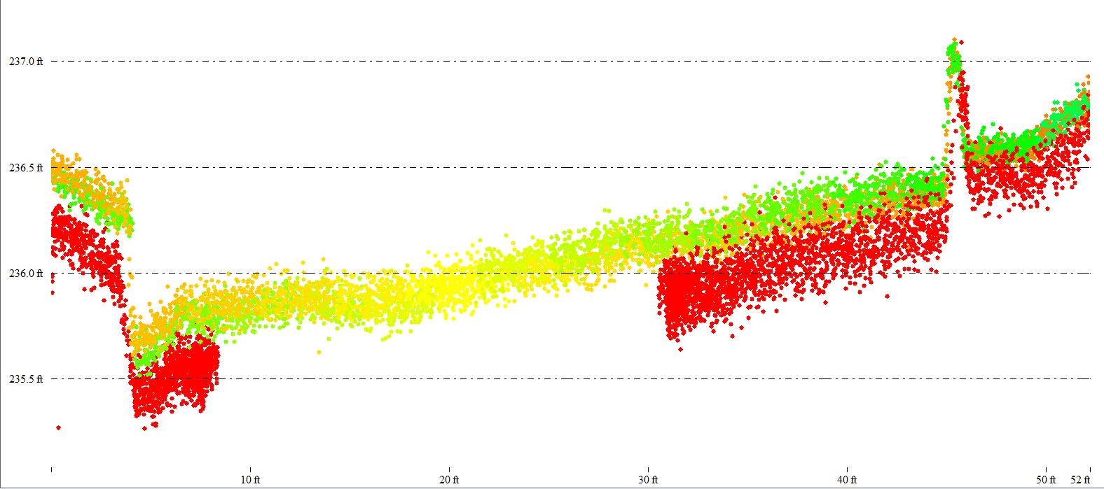
The different colors in this road cross section represent various scan angles along 3 different flight lines. As you can see the more oblique the scan angle (red) the more noise exists in the data. Compare this to the data directly below the sensor (yellow). The increased Lidar overlap will further guarantee you have less noise across the dataset.
Flight Pattern
A single back-and-forth (boustrophedon) flight pattern with nadir gimbal angle is recommended in most cases. There should be no need for off-nadir or cross-hatched missions. Much like photogrammetry, these excessive angles and flight paths can lead to the collection of way more data than you’d ever actually need for a topographic survey, leading to higher noise in the data and longer processing times.
Keep it simple!