Overlap recommendations depend on the sensor you're using. Click the relevant collection medium below to learn more. If your sensor collects both Lidar and Photo data, both sections will be relevant.
Photogrammetry Overlap Best Practices
Flight Plan Best Practices
- 75% / 75% overlap
- Lawnmower (boustrophedonic) flight path, no cross-hatch
- Nadir only, no obliques
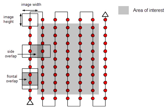
There are many options for photo overlap, and we have tested them all. There is a time and place for each overlap setting, but our recommended overlap is 75% front-lap and 75% side-lap for almost every project, with a single set of back and forth flight lines (boustrophedonic lawnmower pattern), and the camera pointing straight down (nadir) on all photos.
These recommendations are in contrast to more popular suggestions of higher overlap, multiple cross-hatch flight patterns, and off-nadir or oblique imagery. At Aerotas, we have done significant testing on these different types of flight patterns and found almost no improvement in survey accuracy for the vast majority of projects. Instead, it causes an increase in field time, and a massive increase in data processing time, with no measurable benefit in accuracy. There are a few exceptions to this, such as highly repetitive land, like crops and dense vegetation, but for the vast majority of projects, additional overlap provides little to no benefit.
There Is Such a Thing as Too Much Data
There is a common misconception that the higher the overlap, the better data will be collected. Not only does this increase photo amount, and thus processing time exponentially, it also adds a lot of noise to the data. The more overlap there is, the more erroneous matches the software can make, leading to potentially less accurate data overall.
Problems
- More time in the field
- Longer processing times
- Larger / more cumbersome files
- Erroneous matches
These missteps burn time in the field and can 4x your processing time in the office while adding no value to the end product.
Solutions
- Fly higher
- Lawnmower, not crosshatch
- No overlap overkill
- Plan the mission right the first time, and avoid extra flights
We live in a world where human resources, software, and time all cost money, and more data takes more of all of these things. So if your drone program doesn’t have a budget or any project deadlines, then, by all means, collect more data. However, if you want your drone program to take up less time and to cost less money, then use as little data as possible to get the results you need. The surveyors that we work with are not running a research project; they are running a business and need the drone to save them time and money so that they can be more profitable.
This may sound counter intuitive, but at Aerotas we process thousands and thousands of projects and can say with confidence that more data is not always better when it comes to drone data processing. The take away is that you can spend less time in the field, spend less time processing the data, and get a more accurate deliverable by collecting fewer images.
Exceptions to the Rule
There are some situations where higher overlap does actually help;
- semi dense tree cover
- areas between large buildings that need to be captured
these higher overlap settings are not guaranteed to improve the accuracy, but do give it the best shot in these circumstances.
Cross Hatch
A cross hatch pattern or a “grid” pattern can sometimes be helpful in the same ways higher overlap can be, in semi-dense tree cover, as well as in city scape or developed settings where you need to see between buildings.
Off Nadir / Oblique Photos
These are any photos taken from an angle other than straight down. These types of photos are not beneficial for photogrammetry.
Lidar Overlap Best Practices
Since there is a limitation to the quality of the data as the angle of incidence increases we need side overlap to compensate for the data as it gets further away from the sensor laterally. Forward overlap is a moot parameter for lidar given the nature of the data, however, if you have a system (like the L1) you will have options for forward overlap as it pertains to the photos that are captured simultaneously.
In general, Lidar does not need as much overlap as photogrammetry to create a useful dataset (usually somewhere between 20% and 30% side lap will make up for the noise in the high incidence angle data discussed previously).
Since Lidar is not as dependent on matches from swath to swath to rectify a point cloud, it doesn’t need AS much overlap as photogrammetry. So why do we need overlap at all? Because as mentioned the lateral limitations of the data require overlap to reduce noise in the outer areas of each swath. Also, each swath is not perfectly geolocated and will need to be aligned with its neighboring swaths, as well as the GCPs set on the flight for an accurate point cloud to be created, so some overlap is needed.
Before you hit the ground running with your 20%-30% side overlap, you need to consider the sensor you’re using. If your sensor only collects lidar data, this should be ok, BUT, if your sensor collects both photo and lidar data (and you want a usable orthophoto) the overlaps should be adjusted so the photo overlap equals 75% front and 75% side overlap. With the L1 or L2 as an example, 68% lidar side overlap, should give you 75% side photo overlap. The forward overlap parameter, as mentioned, is irrelevant for lidar, but the L1 or L2 give you the option for front overlap to account for the photo capture. This should be set to 75%.
Flight Pattern
A single back-and-forth (boustrophedon) flight pattern with nadir gimbal angle is recommended in most cases. There should be no need for off-nadir or cross-hatched missions. Much like photogrammetry, these excessive angles and flight paths can lead to the collection of way more data than you’d ever actually need for a topographic survey, leading to higher noise in the data and longer processing times.
Keep it simple!
Overlap with Variable Altitude
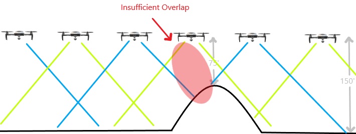
As elevation changes throughout the site, so does overlap. Your drone flies at a set altitude above the elevation that you took off from. You want to make sure your drone flies at least 100’ higher than the highest elevation/ obstacle on the site. If this is not accounted for, you can run into overlap issues when flying over the higher elevation points (shown in the illustration below).
If possible, take off from the highest point on your site, and do not exceed 400’ AGL.
Another way to deal with elevation change is to use a "Terrain Awareness" feature. The video below dives into why and when you should use this incredibly useful feature.