Linear Flight Planning for Pipelines, Roads, and Corridors
The best path to reliable data collection
A linear mission is any mission where the area of interest is a narrow strip of land. E.g. pipelines, roads, and corridors. The area of interest is typically 50-500' wide and can be miles long.
Most mission planning software applications have a linear mission planning tool to help you create an optimal linear mission, but knowing what the ideal parameters are and why we use them, will help ensure you are collecting the most reliable data possible.
Flight Lines
The way your flight lines are oriented and the number of them is a primary parameter for the adequate collection of data on linear missions.
Flight lines should always be oriented lengthwise down your corridor. This will create the most consistent photo capture pattern and keep the drone flying in one direction longer, which is more efficient than changing directions every 5 seconds.
With this in mind, there should be a MINIMUM of 3 flight lines total to capture your corridor; one on the left, one down the middle, and one on the right. This adds redundancy to your data in order to guarantee you have enough photo coverage to process properly. Sure, you could get away with 2 flight lines, but as soon as a few of those photos in a row are uncalibrated, you are hung out to dry and will have to fly the whole site again to get usable data. To reliably achieve three flight lines, set your overlap and flight altitude first, then toggle, "include centerline" in DJI flight planning apps. If your swath is too small, the app may suggest only one flight line. In cases like this just adjust your total swath until you see 3 flight lines.
Bottom line:
- Fly lengthwise
- Fly at least 3 flight lines
Overlap & Altitude Settings
Overlap should be set to 75% front and 75% side lap. This recommendation is the same for all photogrammetry projects. 75% overlap allows enough coverage for an entire flight line to be missed without compromising the data, yet it isn’t so high that the data collected is oversaturated and artifacts begin to occur.
Overlap Best Practices
https://www.aerotas.com/overlap-flight-pattern
So what altitude should you fly at? That is going to be first and foremost dependent on what your accuracy tolerances are for the site. Then, how much time you have allotted for the mission to be flown, as well as perhaps how narrow you need to keep your corridor.
Some corridor missions are tight and may push up against a major highway, or some other restricted area that you are not allowed to fly over. The flight altitude will determine how narrow or wide your 3 flight lines are.
The lower you fly, the tighter your accuracy can be, but the more data you'll collect and the longer your flight will take. In contrast, if you do not have space restrictions and all you need on your corridor is 1’ contours, you can fly the mission as high as possible (no higher than 400’)! This will reduce the time you spend in the field exponentially by allowing you to cover a lot more land, faster.
GCP Layout
Non-RTK Layout
GCP layout patterns change slightly for linear missions but are still based on the same principles as regular polygon missions. The goal for every photogrammetry mission is to anchor the model to the real world, which means setting GCPs evenly throughout the entire site while making sure all of your GCPs are overflown in order to be included in enough photos.
How linear missions differ, lies in their elongated shape. It is not simply enough to place a row of GCPs along the length of your linear mission. The reason being, if the GCPs are laid in a straight line, the entire model has the possibility of “rolling”. This occurs because the model is only anchored on one plane. Think of it as laying a board on a single string (the string being the row of GCPs and the board being the model). Using one string, it is going to be extremely difficult to get the board to balance perfectly, it will likely tip one way or another. We need a GCP layout with more dimension to it in order to verify the model is true.
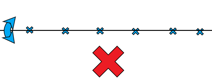
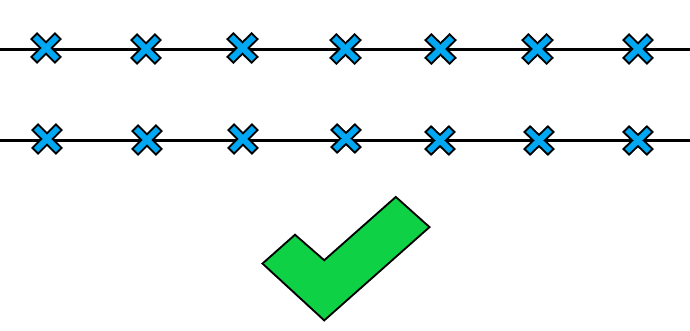
Therefore we recommend setting the GCPs in pairs along the length of the mission, so instead of having one “string” you have 2 “strings”, one up the left side and one up the right side.
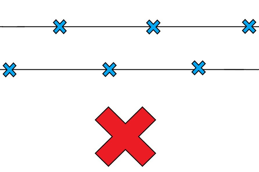
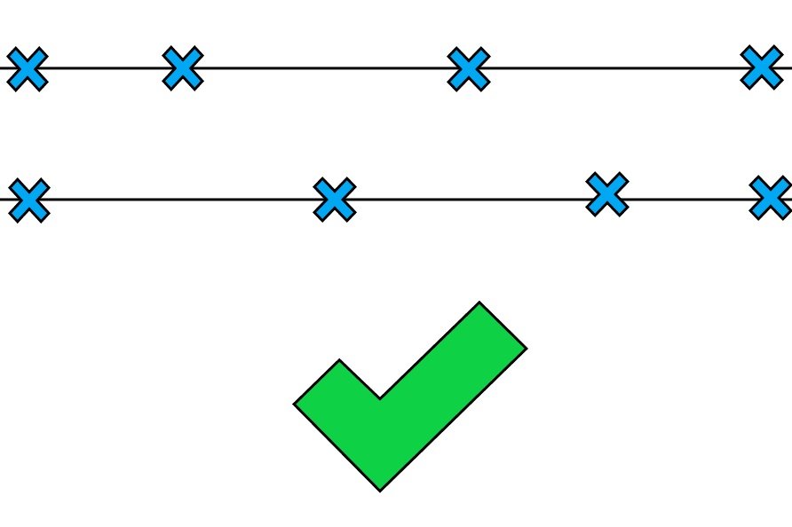
You may ask, “what about alternating sides of the corridor instead of setting redundant pairs?”. While only adding alternating GCPs creates a more dynamic layout, it can actually allow the model to twist at the ends, leading to inaccurate data. To account for this, you can use a hybrid approach, setting solid pairs on either end of your corridor, and alternate GCPs throughout the interior portion of your project. Keep in mind, if you use this method, you must ensure your alternating GCPs are accurately measured, marked, and anchored the first time, because there is no internal redundancy built in with the alternating GCP method.
GCP pairs or alternating sides should be placed every 500-1000’ along the entire length of the mission, depending on how high you plan to fly for non RTK projects.
- 400’ mission- 1000’ spacing between pairs
- 150’ mission- 500’ spacing between pairs
RTK Enabled Layout
For RTK-enabled aircraft, the rules are a little different. Since the RTK-enabled photos are already geolocated to around 0.1’ X, Y, and Z, we usually do not have to worry about the model rolling. That being said, it’s always good practice to use pairs at the ends of the project for added redundancy/checks. As far as GCP spacing goes, we would recommend splitting your project into 3000’ sections and placing a GCP (or pair) every 1500’. The 3rd GCP or pair on each segment will act as the first GCP on the next segment in the area of overlap. It’s usually good practice to have 3 GCPs set for every base station move, but advancements in processing and GPS technology relax even this parameter.
The above parameter IS redundant but is good practice as it helps avoid site revisits and increases reliability. If you are in a pinch for time/resources, you can get away with a leaner GCP layout (creating a larger flight segment allows you to space your GCPs further apart). Just keep in mind, that you are still bound by the Part 107 visual line-of-sight (VLOS) requirements.
Segmenting the Mission
Due to the visual line-of-sight (VLOS) requirements and battery limitations, segmenting linear missions is almost always a must. There are only 2 scenarios where you would not need to segment a linear mission; if the entire length of the project is less than 3000’, or the mission requires fewer than the number of batteries you have at your disposal.
To segment the mission we need to first think about visual line-of-sight (VLOS). Most small drones become incredibly difficult to locate with the naked eye at any distance greater than 1500’, however, larger drones like the M400 RTK can be seen at much greater distances (up to 3000' or more in some cases). Take whatever you decide is your maximum visual line of sight, multiply that by two, and take off from the center of that. Keeping this distance divisible by 1500' makes the GCP planning even more seamless.
Use “Cutting Distance” if able
Most (DJI) surveying drones have a feature built into their linear mission plans called “cutting distance”. This feature will segment your linear mission into equal pieces based on the parameter you define in the software. If you have this feature available to you, this is the cleanest and most efficient way to ensure your flights stay within sight-limited or radio-limited range.
Manually Connecting the Segments
If you don’t have a “flight band cutting” option, manually segmenting the missions will be necessary. Segmenting the mission allows us to tackle missions of any length by sectioning them into bite-sized pieces.
You’ll most likely want to create individual linear missions defined by individual kml polylines uploaded to your controller if able. Otherwise, you can manually create the lines in the mission planning software.
General Rules for Segmenting Missions
Ensuring the segments will process together relies on a few factors, the more of these factors you have going for you, the easier the segments will stitch together.
100’ of Overlap Between Segments
Having 100’ of overlap between the segments allows for features to be matched in both segments and will give the model plenty of overlap to seamlessly stitch the segments together.
GCPs in the area of Overlap
There should always be at least 1 GCP in the area of overlap. This will further ensure that both segments are snapped true to the model from the same point. This eliminates “shelving” that can occur when two segments are merged from different flights on different days.
Fly in similar lighting/environmental conditions
Photogrammetry software looks for key matches, and if the lighting is different, the features look different and two separate surfaces can be generated, causing shelving and inaccuracies where the two segments meet. Similarly, the same issue can occur if the environmental features change, such as a lawn being mowed or leaves falling between the time the segments are flown.
It is always best to fly segments back to back in a timely manner to avoid environmental changes that can cause issues in processing.
Complicating Factors
Change in elevation
Change in elevation throughout a particular segment can cause overlap issues, depending on where you take off relative to the elevation change. Always try to take off from the highest point of the segment, or at least no more than 1/4 of your flight altitude below the highest point. This may mean not taking off from the middle of the segment. To remedy the visual line of sight issue, you can use a visual spotter to monitor the drone as it reaches the far end of your segment.
Another solution is to use Terrain Awareness. Any modern autopilot worth anything in the commercial industry today will have a Terrain Awareness feature that allows the drone to remain a set height above the terrain throughout the flight, which keeps overlap consistent. If you use Terrain Awareness you can take off from the middle of each segment regardless of elevation change.
Why You Should Use Terrain Awareness
GCP location restrictions
Sometimes the perfect GCP layout is not possible due to private property issues, inaccessible areas, or a number of other reasons. This is ok, the GCP layouts we suggest for NON-RTK aircraft have sufficient redundancy built-in. If one pair of GCPs is unable to be set on either side of the corridor, it is perfectly ok to just set one in the middle, or even one on one side or the other. The main thing to avoid is setting control in a straight line. So long as there is variation along the corridor, the model should process fine.
Spacing is also not absolutely set in stone. The only upper limit is the 1000’ space between GCPs for NON-RTK planning. You do NOT want to set a GCP pair any further than 1000’ from the next in any scenario. You can get away with +/- 100’ distance between pairs up to 1000’.
Software Solutions
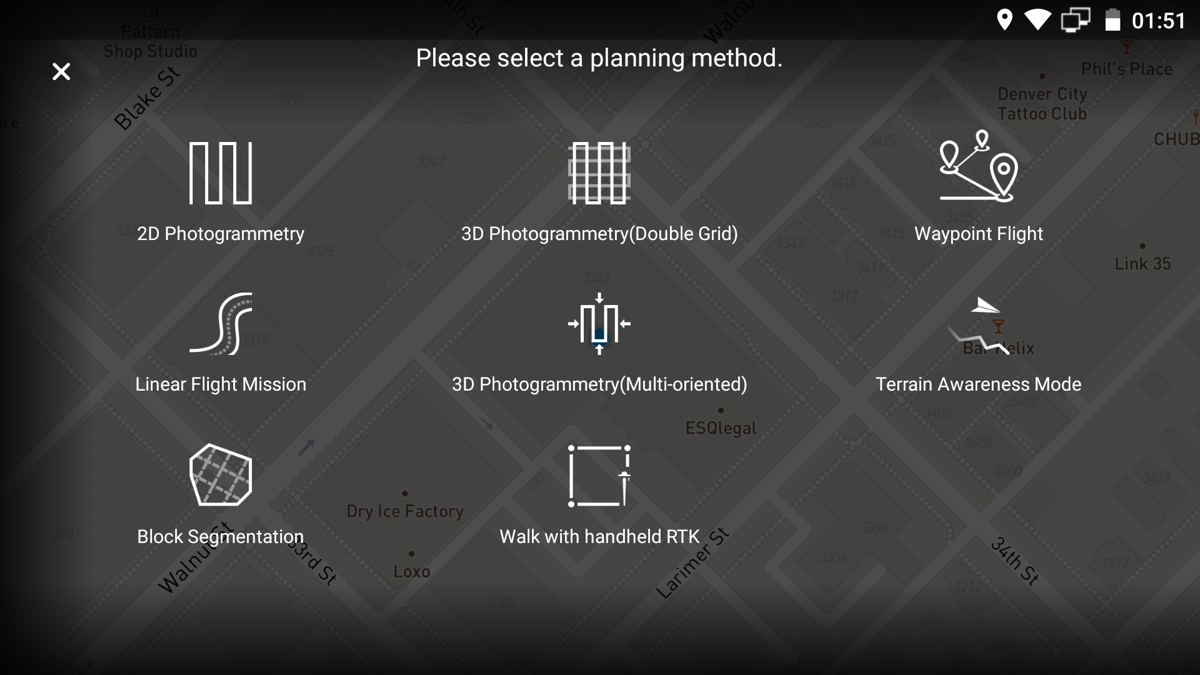
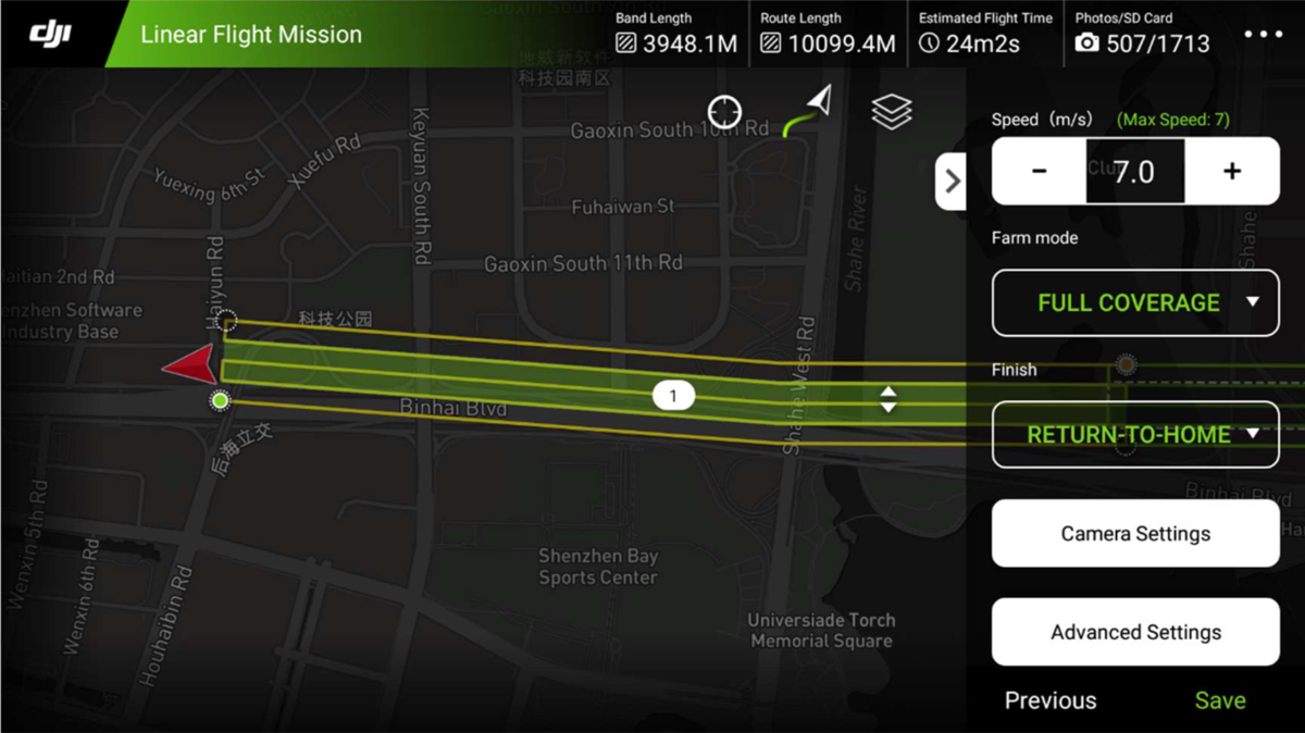
For those of you flying the Phantom 4 RTK, you will want to select the Linear Flight Mission planning method and make sure that you are in Full Coverage flight mode.
Steps:
- Click Linear Flight Mission
- Tap the map in order to draw a line
- Create your desired swath by adjusting the expansion distance left and right
- Set your altitude and overlap. E.g. 200’ AGL and 75/75 overlap
- Select Full Coverage flight mode
- Enter a Mission Name
- Invoke Mission
DJI Pilot (M300RTK)
DJI Pilot is the default mapping software that comes with the M300RTK. It too, has a linear mission planning function that works virtually identical to the GSRTK function.