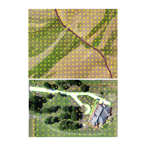
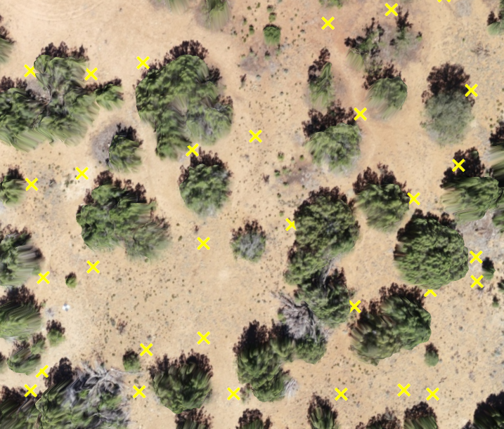
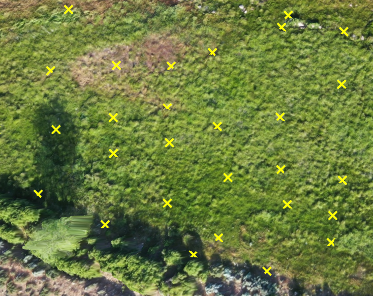
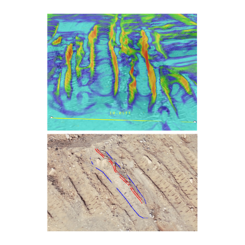
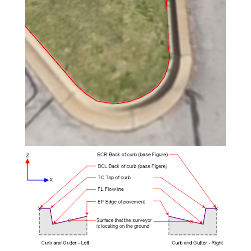
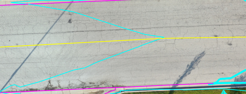
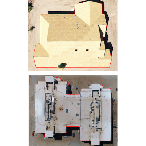
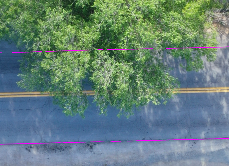
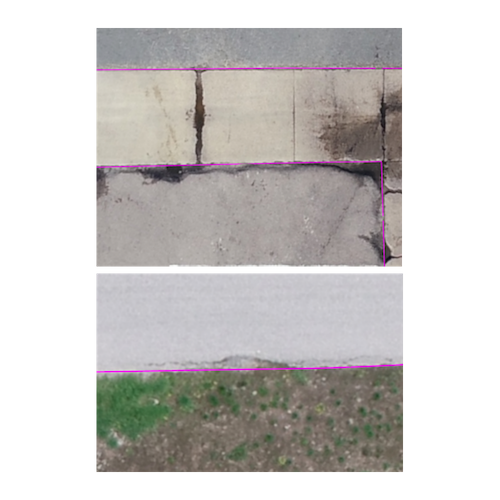
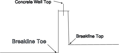
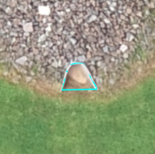
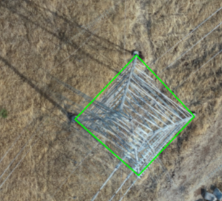
How Features are Marked
This page gives a high level overview of how our features are marked within our deliverables. If you’d like more specific and detailed information about how features are marked, download our comprehensive guide below!
We adjust the density of points depending on the terrain. We will never use more than approximately a 30’ distance between points but will increase point density as required to represent the actual terrain appropriately.
In areas of sparse vegetation where patches of bare earth are visible, the bare earth portions will be marked, and the topographic points will be labeled as standard topo points.
In areas of moderate vegetation where there are no areas of bare earth clearly visible, the lowest elevation points in the area will be marked, and the topo points will be added in the vegetated topo points layer.
In areas of dense vegetation where no reliable terrain information can be derived (i.e. dense tree cover), then a polygon of “unreliable information” will be drawn surrounding that area.
Breaklines will be added in a density required to faithfully represent the terrain in real life. In areas of significant noise (i.e. dirt roads with numerous tire ruts) a density of no more than 4 parallel breaklines per 10 horizontal feet will be drafted.
Curbs are captured with 2 lines in 3D, the Edge of Road and the Back of Curb. It is advised to offset from those two lines to get the rest of the curb geometry. When Edge of Road is not present, the drafter may use a breakline to represent the curb geometry. All curbs will have 2 lines that represent its geometry.
Centerline is drafted along the center of a roadway. An additional breakline may be added if the centerline of the road is not the exact crown.
Building footprints cannot be reliably marked from photogrammetry data. Instead, we mark the dripline of any building that is present in the linework.
When lines go under trees/eaves, wherever possible, we will continue the breakline interpolated underneath the tree. There may be error when interpolating lines, as the line may not continue in real life. We will not interpolate underneath gaps of 20’ or greater; instead, we will leave it blank. When lines (e.g., dirt, asphalt, concrete, etc.) are ambiguous, we have the discretion to estimate what the boundary would be, and there may be up to a foot or more of ambiguity.
In areas with slight to moderate damage to concrete, asphalt, or other hardscape, the drafting will represent what the ideal concrete line would have been, not every individual piece of damage, unless otherwise requested. For significant road damage (>3’ damaged or more) then drafting will follow the actual, damaged line.
Utility access panels and other utilities are outlined with a polygon. Because it is impossible to tell from the air what type of utility it is, they are all marked in a “utilities” layer.
Fire hydrants are marked with a single point in a fire hydrant layer. This is marked as a 2D feature.
Lamp posts, lighting fixtures, and power poles are marked with a single 2D point at the point where the pole meets the ground.
Brick walls, concrete walls and fences are captured in 2D with one line down the center. Any elevation change, such as with a retaining wall, is captured in 3D with breaklines.
Shear faces and walls are captured in 3D with a top and toe breakline. Please note that data at the bottom of a shear wall or face can be unreliable due to the limitations of photogrammetry and may not be captured if the drafter determines that it is unreliable data.
X-2D-Edge-Water is drafted based on the visible 2D edge of water particularly when there is too much obstruction in the data or bad data to draft as an accurate 3D line. Then, breaklines and points are used to create an accurate surface.
X-3D-Edge-Water is used when the edge of water accurately aligns with the surface breaklines.
Bleachers may include the following: ramp, railing, and steps (see screenshot). Handrails along ramps and stairs are only drafted outside of the bleacher limits.
Solar-Panels are drafted as groups of panels. Solar Panels that are not on the ground such as on building roofs are excluded from drafting unless the “Roof Features” option is requested as an Add-On at the time of quoting. Additionally, solar panels that are part of a solar farm are not drafted unless a custom request was made at the time of quoting.
Transmission-Towers are drafted with a polygon connecting the tower base legs together.