Aerotas Product Specifications
the right deliverables for your project
Features Not Marked by Default
Individual plants & trees
Vehicles, trailers, & movable objects
Tops of buildings / Rooflines
Anything underneath dense vegetation, eaves, overpasses, etc.
Anything that can’t be seen from the air
Technical Specifications
2D vs 3D Points
Elevation points are stored as COGO points in Civil3D.
Any points included in “Topographic” layers will be marked in 3D, and any points included in “Planimetric” layers will be marked in 2D.
Symbols are added for manholes, fire hydrants, power poles, and light poles to improve visibility beyond a single point. Symbols are used in every dataset unless requested.
Elevation points are annotated with their elevation.
2D vs 3D Polylines
Any polylines included in “Topographic” layers will be marked in 3D, and any polylines included in “Planimetric” layers will be marked in 2D.
Areas with no data, uncertain data, and heavy vegetation will be marked with 2D polylines.
TIN Surface
A TIN surface is created using all of the topographic data on a project, and does NOT include any of the data in the “Planimetric” layers.
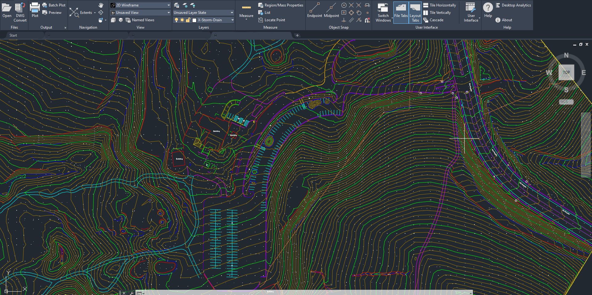
Contours are displayed both as a layer with individual polylines, as well as a visible portion of the created TIN surface.
Contours
1’ contours are provided standard on all projects, with 5’ contours as the major contour interval. By default, we do not apply any smoothing algorithms to the contours, and the exact contour associated with the manually drafted TIN surface are used. Contour lines are annotated with the elevation of the contour itself.
Contour lines are provided in 3D with vertical values associated with them.
Roof Elevation Points
Roof elevation points are annotated with their elevation.
Roof elevation points will NOT be included as part of the TIN surface.
Roof elevation points exclude roof structures (chimneys, stairway towers, AC units, etc.).
A minimum of 5 roof elevation points will be provided by default.

